Getting Started Guide: 2D Views in the Models Tool
Objective
To set up the Procore plugin and Models tool in order to use the 2D Views feature in the model viewer on the Procore app for iOS.
Things to Consider
- Required User Permissions:
- 'Admin' level permissions on the project's Models tool.
- Additional Information:
- The 2D Views feature is only available on the Procore app for iOS devices.
Prerequisites
- The Models tool must be active on the project.
- You must have access to the following Autodesk® programs: Navisworks® (Manage or Simulate) and Revit®.
Video
|
|
Steps
Follow the steps below to use the 2D Views feature for the first time:
- Download or Update the Procore App on an iOS Device
- Download the Procore Plugin on a Computer
- Publish a Model to Procore
- Export Grids from Revit
Step 1: Download or Update the Procore App on an iOS Device
- If the Procore app is not already on your iOS device, you will need to download it from the App Store. See How do I download Procore's iOS mobile application?
- Open the Procore app.
- Confirm that your app version is 2021.0412 or later.
- To see what version you are currently using, tap Settings and scroll to the bottom. The version number is shown under your Procore email address, next to 'Procore for iOS'.
- If you need to update the app, go to the App Store on your device to initiate the update. See Update the Procore iOS App.
Step 2: Download the Procore Plugin on a Computer
See the full Download the Procore Plugin for the Models Tool tutorial, or click below to view the steps.
Show/Hide Steps
Step 3: Publish a Model to Procore
See the full Publish a Model to Procore tutorial, or click below to view the video and steps:
Show/Hide Video and Steps
Follow the steps below to publish a model to Procore.
- Step 1: Launch the Procore Plugin in Navisworks®
- Step 2: Select the Publish Action
- Step 3: Enter Model Information
- Step 4: Configure Viewpoints
- Step 5: Add a 2D Sheet
- Step 6: Map the 2D Sheet to the Model
Step 1: Launch the Procore Plugin in Navisworks®
- In Navisworks®, click the Procore tab to open the plugin ribbon.
- Click Publish to open the Models window.
Step 2: Select the Publish Action
In the Models window, choose one of the following options:
- To publish a new model, click New Model.
- To publish a new version of an existing model, hover over the model in the list and click Publish Version.
Step 3: Enter Model Information
Enter information about the model as follows:
- Choose the appropriate option:
- For a new model, enter the Procore display name in the Model Name field.
OR - For an existing model, keep the existing name.
- For a new model, enter the Procore display name in the Model Name field.
- Select the Model Status from the drop-down list:
- Coordination. For reference only. Not approved for construction.
- Construction. Fully coordinated and approved for field installation and layout.
- As-Built. Updated to reflect final, field-verified conditions.
- Automatic Revisions:
- Select the box to automatically publish a new revision when a new version is uploaded.
- Select an option to set your 2D Mapping preference:
- Map Drawings (Recommended).
- Click Next.
- Publish Model without mapping drawings.
- Click Save Changes.
- Map Drawings (Recommended).
Step 4: Configure Viewpoints
Set the Home Viewpoint
The Home Viewpoint is the model's default starting view and thumbnail image. For best results and easy navigation, choose a clear, general overview of the project.
- Set the initial viewpoint:
- In the viewer, navigate the model to your desired starting position.
- Click Add.
- Click Save to confirm.
- Optional: Update an existing viewpoint:
- Navigate the model to the new position.
- Click Edit.
- Click Save to apply the changes.
Add Saved Navisworks® Views (Optional)
You can upload specific viewpoints to make them available in Procore.
- Add a saved view:
- Click Add.
- Mark the checkbox next to each view you want to upload.
- Click Add to confirm your selections.
- Optional: Remove a saved view:
- Click the delete (x) icon next to the viewpoint.
Step 5: Add a 2D Sheet
- On the Map Drawings to Model screen, make a selection from the dropdown menu for each of the following required fields:
- Level. Select a location level from the drop-down menu.
- Drawing Area. Select a drawing area from the drop-down menu.
- Drawings. Select the relevant drawing(s).
- Click Next.
- Now, you must map the sheet(s) to the model. See Step 6: Map the 2D Sheet to the Model.
Step 6: Map the 2D Sheet to the Model
This step aligns the 2D drawing with the 3D model by asking you to select two common reference points on each.
- Select reference points on the 3D model:
- Click Map Model to begin.
- Select two reference points on the 3D model. The points will be labeled 'A' and 'B'.
- To clear your selected points, click Reset All.
- When you are satisfied with your points, click Save.
- Select matching points on the 2D drawing(s):
- Click Map Drawings to begin selecting points on the drawing(s).
- Select the same two reference points on the 2D drawing that correspond to points 'A' and 'B' from the model.
- The rest of the selected drawings will be automatically mapped
Note: Reference points are saved automatically, but reviewing the drawing turns the checkmark blue.

- The rest of the selected drawings will be automatically mapped
- To clear your selected points, click Reset All.
- To clear the selected points on one drawing, select the drawing and click Reset Mapping.
- Click Save to confirm the points.
- Click Done Mapping when finished.
- Click Save Changes.
Step 7: Publish the Model
Before finalizing the model, decide whether to process it using Procore's cloud servers (recommended) or your local computer.
Important
Use Section Boxes in Navisworks® to publish specific areas or views of your model. See Add a Section Box to a Model. Section Planes are not supported and can't be published to Procore.- Choose your publishing method:
- Cloud Publishing (Default & Recommended)
- How: Leave the Publish Locally checkbox cleared.
- Description: This is the fastest method. Procore's servers do the heavy lifting, which frees up your computer. You can monitor the progress on the Uploads tab in the Procore BIM plugin.
- Local Publishing
- How: Mark the Publish Locally checkbox.
- Description: This option is significantly slower. Procore recommends using it when publishing a locked model file or when troubleshooting issues with the Navisworks® Appearance Profiler.
- Cloud Publishing (Default & Recommended)
- Finalize and view:
- When ready, click Publish.
- After the model has successfully processed, a confirmation message will appear. Click Done.
- View your model in the Models tool on the Procore web or mobile app. See View a Model (Web), (iOS), or (Android).
Step 4: Export Grids from Revit
The Navisworks API does not support the ability to publish grid lines, so you must use Revit to export the project grid lines. This is a VERY important step and should be done by a team member that can QA/QC the origin and validate that the grids are in the right location prior to the field referencing them for installation.
- Open a master coordinate file or any project file with the construction levels and grids for your project.
- Navigate to the Procore tab in Revit and select the export grids button from the ribbon.
- Use the drop-down menu to select the company and project to export grids.
- For the Coordinate System, select Internal or Shared coordinates.
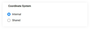
Important! This should match your federated model coordinates published from Navisworks. - Click Add Grids for all models that share the same grid system.
Note:- Only one set of grids can be exported per published model.
- The 2D View
 icon in the mobile viewer will NOT show if no grids are associated with the model. If there are grids, the 2D view option will show when the wall object is selected in the Models tool.
 - Gridlines can be turned on or off by 'Admin' level users in the Settings area of the mobile viewer. See Settings: Models (iOS).