View 3D Models in the Estimating Tool
Objective
To view 3D models in the Estimating tool.
Background
A takeoff extracts quantities from a drawing or model and associates with items in your cost catalog to create estimates. You can use a variety of tools to adjust the model to see the information you need.
Things to Consider
Prerequisites
Steps
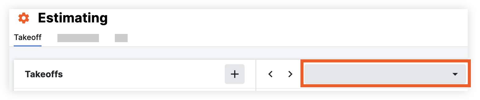
- Navigate to the project's Estimating tool on app.procore.com.
Note: The Estimating tool automatically opens to the Takeoff page. - Click the drawing drop-down menu.
- Click the Models tab.
Note: This pulls model files from the project's Documents tool. See Upload Files or Folders to the Project Level Documents Tool. - Click the model.
Fly Tool
Navigate the model from the camera view at varying velocities.
- Click the Fly
 icon (or press F on your keyboard)
Note: The velocity of the camera movement will increase or decrease depending on how far you move the cursor on your mouse.- Left-click + drag up or down: Click the left mouse button and drag the cursor up or down to move the camera into or away from the model.
- Left-click + drag left or right: Click the left mouse button and drag the cursor left or right to rotate the camera clockwise or counterclockwise.
- Scroll: Press the scroll button on your mouse and scroll to rotate the camera up or down.
- Middle-click + drag: Press the middle click button on your mouse to move the camera perpendicularly.
Tip! You can also perform this action by pressing and holding the space bar on your keyboard and clicking the left mouse button at the same time. - Right-click: Click the right mouse button to select an object and access the following options from the drop-down menu:
- Click Hide Object to hide the selected object from the view.
- Click Hide Similar to hide objects with the same name.
- Click Isolate to isolate the selected object in the view.
- Click Isolate in X-Ray Mode to activate X-Ray mode, which will show the selected objects while simplifying the rest of the model.
- Click View Properties to view properties for the selected object.
- Click Zoom to Selection to zoom to the bounding box of the selected object.
Measure Tool
Measure the distance between two objects.
- Click the Measure
 icon.
icon. - Select two objects on the model
Orbit Tool
Rotate the camera from a fixed point.
- Click the Orbit
 icon (or press O on your keyboard).
- Left-click on an object: Click on an object with the left mouse button and drag the cursor left or right to rotate the camera around the click point.
- Left-click on an empty space: Click the left mouse button on an empty space to rotate the camera around the center of the model
- Middle-click + drag: Press the middle click button on your mouse to move the camera perpendicularly around an object.
Tip! You can also perform this action by pressing and holding the space bar on your keyboard and clicking the left mouse button at the same time. - Right-click: Click the right mouse button to select an object and access the following options from the drop-down menu:
- Click Hide Object to hide the selected object from the view.
- Click Hide Similar to hide objects with the same name.
- Click Isolate to isolate the selected object in the view.
- Click Isolate in X-Ray Mode to activate X-Ray mode, which will show the selected objects while simplifying the rest of the model.
- Click View Properties to view properties for the selected object.
- Click Zoom to Selection to zoom to the bounding box of the selected object.
Sectioning
Visualize and analyze the internal structure of a building (such as the placement of pipes, ducts, and electrical systems).
- Click the Sectioning
 icon to open the sectioning tool.
 - Click and drag (up and down or left and right) to adjust the section box and slice through the model.
- Click the Section Box drop-down menu to access the following actions:
- Display Planes: Shows or hides the section planes.
- Reset Planes: Resets the section planes.
- Zoom to Box Extents: Zooms to show the extents of the section box.
Show or Hide Model Objects
- Next to the model object in the list, take one of the following actions:
- Click the show
 icon to hide the object in the model.
 - Click the show
 icon to hide the object in the model.
- Click the show
X-Ray Mode
You can view the model in normal and X-Ray modes. X-Ray mode is helpful when you need to focus on certain objects without other objects blocking your view.
- Select the model objects in the list that you want to view.
- Click the X-Ray
 icon in the toolbar.
OR
Right-click on the objects and select Isolate in X-Ray Mode.